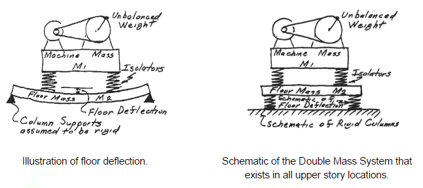
has a smaller deflection than the floor system on which it is sitting. For example, if we decide to isolate a 3600 rpm. pump to eliminate 95% of the vibration, we would pick mountings with deflections of about 0.05″. Floors are designed with an allowable deflection which is normally as much as 1/360 of the free span. Twenty foot bays are small today, but assuming this pump were located in a 20′ bay, the floor deflection might be as much as 1/360 x 240″ or approximately 0.666″. If the floor had only half the maximum allowable deflection, it would still be 6.5 times less stiff than the isolator we have selected. The introduction of this stiff mounting will do nothing for the floor isolation. There are more complicated equations that can be used to theoretically solve any vibration application problem. This type of equation is useful occasionally to find out if we are working in the proper direction when a new system of isolation is developed. This type of analysis has shown that to get back to the theoretical figures shown by the Efficiency Chart, the isolator deflection has to be as much as 6 – 8 times the floor deflection when the slab is light. While these numbers may sound far fetched, in actual solutions of existing problems, we have used mountings with as much as 3″ of static deflection to solve a problem where the theoretical charts showed us that a 3/8″ deflection should have been quite satisfactory. Today’s deflections are selected on an empirical basis based on actual field experience. These are practical values that are necessarily broad in scope. In some cases they may be more than is actually required to solve a particular problem, but a commercial vendor must deal in broad terms. On large critical jobs it is often important to rely on the impartial professional judgment of a qualified acoustical consultant to make a specific job analysis and sort out the exact requirements for each piece of equipment depending on its size and location in a particular type of structure. The commercial vendor is dedicated to his own company and usually suffers from limited acceptance of his competitor’s best offerings. The professional is free of this prejudice and can make his selections from designs submitted by the entire industry. A consensus of the deflections we have worked to for various floor spans are shown in the Selection Guide at the end of the Engineering Specification Bulletin. This need for higher deflection materials has caused reclassification of products: Pad materials, be they neoprene, cork, combinations of cork and neoprene, fiberglas, sisal fibers, felt, lead or any other material, provide limited deflections. These deflections are normally 10-20% of the pad’s thickness. Therefore, pads are good for high frequency noise breaks, and since their deflections are almost always small in comparison to upper floor deflections, their use should generally be confined to basement areas, non-critical jobs or situations where job costs must be kept to an absolute minimum regardless of performance. Neoprene mountings and hangers fall into the 0.20″ to 0.50″ deflection range. They do provide sufficient static deflection to offer protection under small high-speed equipment such as close-coupled pumps up to 3 HP, vent sets, small heating ventilating units, etc., where the unbalanced forces are so small that in all probability only a noise break and minor vibration relief need be provided. Neoprene hangers are sufficiently effective for isolation of steam lines where there is seldom any real vibration, but only high frequency whistles and noises of that nature. While neoprene mountings and hangers do have their place as noted, there is a tendency for specifications to call for spring mountings throughout because the dollar difference between the neoprene mountings and small spring mountings is a very small percentage of the overall job cost. Neoprene hanger elements are often used in series with springs, because the neoprene element will do a far more efficient job of eliminating the high frequency noises than the spring alone. Steel spring mountings are by far the most widely used commodity on critical jobs today. Steel springs are practical through 5″ of static deflection and even more on specific occasions. Springs provide an easily variable design medium, and steel spring installations are as permanent as the machine itself when selections are made within proper stress values. Most modern isolators are simply steel springs that have been designed with large enough diameters to provide stability without the need for a supplementary, often detrimental, housing. They are generally manufactured with an adjustment bolt and a pad made of neoprene or some other material in series with the spring to attenuate the high frequencies. A relative newcomer to the field of air conditioning equipment isolation is the Air Spring. In broad terms an Air Spring is merely a large bladder that is manufactured in a configuration to withstand as much as 100# of air pressure and provide a stable support point for the equipment. By properly shaping the air spring, small units can be designed to provide the equivalent of 6” to 7” of spring deflection in the steel spring series. Since the walls of the air spring are constructed of rubber, there is no possibility of the type of spring resonance sometimes found in the coils of large deflection, large diameter steel springs. Air springs have the advantage of supporting a wide range of loads merely by varying air pressure, and the spring frequency is a function of the shape rather than the pressure. In general, air springs are installed with a replenishing air supply to compensate for leakage, or expansion and contraction where there is a wide temperature variation. Height Control valves are provided to maintain elevation and compensate for external forces such as fan thrusts. Since these complete installations are generally more expensive than steel spring isolation methods, air springs are generally reserved for extremely critical locations as recommended by an acoustical consultant. Supplementary steel or concrete equipment bases are most often used to keep equipment in alignment. This may be true when the base is used to tie a fan and motor together, or provide the common base for a turbine-driven compressor. Bases may also be used to stiffen an existing base such as a cast iron pump base, provide stability for tall machines such as absorption machines, or tie a complete package together as in the case of a long, many-sectioned heating and ventilating unit. In many cases, bases are constructed of steel rather than concrete because they can be shipped to the job as a complete welded assembly and installed without involving more than one trade. Their light weight as compared to concrete, lessens the floor burden and reduces the need for strengthening the floor slab. When steel bases are used, however, it is most important that they are made sufficiently rigid to provide support for the mechanical equipment and do not resonate at the frequency of the equipment they are supporting. The best approach to this is the use of steel beams as the base members, and we would suggest a depth of framing equal to 1/10 the longest dimension of the base. Cross-framing may be used for additional stiffening especially on large HP direct-drive units. Floating concrete bases are recommended for pumps because pump bases are designed for grouting to concrete floors. The use of a floating concrete base provides a grouting surface and the extra stiffness the pump base requires. When stiffness is the only factor, a concrete depth equal to 1/12 the longest dimension of the base is usually satisfactory. Concrete bases are also used for inertial purposes when an increase in mass is necessary to resist either the unbalance of the equipment or external forces. The classic example of unbalanced equipment is the single or double cylindered vertical or horizontal slow-speed air compressor. These large bore, long-stroke machines usually run at 350 rpm and they can be only partially balanced. The weight of the concrete base is calculated from the unbalanced force information supplied by the compressor manufacturer. These concrete inertia bases are 5 to 7 times the weight of the compressor in order to bring the motion down to acceptable limits. Concrete bases can be used to offer resistance to external forces such as fan thrust. We have found that this is particularly important when isolating high pressure cabinet units because there is a combination of back vacuum and fan thrust which tend to displace them. Concrete bases are suggested for the isolation of high pressure fans above 6“static pressure. The weight requirement falls somewhere between 1 to 3 times the weight of the equipment and must be determined in each situation. While simple steel bases are generally more economical than concrete filled bases, most of our specifications call for concrete as a more foolproof broad application method. Flexible hose should be installed horizontal and parallel to the axis of rotating equipment. This allows the hose to flex in the transverse direction. All hoses are quite stiff axially. Butyl rubber hoses have a better chance of reducing pipe wall transmitted noise, but we have found no hose particularly effective against water-borne disturbances. When butyl hoses are used, we would suggest that Control Cables are installed parallel to the hose to prevent elongation and possible hose failure. Stainless steel or bronze metallic hoses are recommended for those services where the static pressure or temperature exceeds the capability of the rubber materials. While flexible hoses are not complete protection against pipe line noises, they do provide flexibility at the points of connection to the mechanical equipment. This reduces stresses to the flanges and allows the isolated equipment to move freely on the springs. Since noises transmitted to pipe lines will travel for unpredictable distances, the trend is to isolate mechanical pipe lines throughout their run. This type of isolation is normally provided by combination spring and neoprene hangers. While all connections to high pressure ducts should be made flexible, these connections are not completely successful either. There is enough air turbulence in high pressure systems to vibrate the ducts and cause possible transmission to the structure. Ducts are normally isolated by 1″ deflection spring hangers that are installed up to 50′ from the fan discharge. The following specifications describe commodities that are now common to the industry. They are available from many of the manufacturers. Our selection guide refers to these commodities with suggested minimum static deflections as noted. This guide is provided as a broad introduction to the field of specifications and we recommend its use to develop a general feel for the subject and application on projects of an everyday nature. We hope that your being familiar with these designs and recommendations will help you in your work and that we can continue to contribute to the general pool of vibration control information.
 +(84) 839 606 568